$\newcommand{orange}{\color{orange}}$
IQ: What happens to stationary and moving charged particles when they interact with an electric or magnetic field?
- Stationary charged particles do not experience a force in a magnetic field $(F = qvBsinθ),$ but they do experience a force in an electric field $(F = qE).$
- Moving charged particles experience a force both in a magnetic field and in an electric field.
- If a charged object is projected into the field it will experience a force (acceleration through change in speed, direction or both) as a moving charged object (eg: current) induces a magnetic field as per Ampere-Maxwell law thus, the two fields will interact with each other.
- Similarly, moving and stationary massive particles in a gravitational field experience a force.
- Charged particles projected into a uniform Electric field have a parabolic trajectory or undergo Uniform Circular Motion.
- Fields are illustrated using lines travelling from + to – (Electric field) or North to South (Magnetic field). For 3D uniform fields going into the page, field lines are illustrated by evenly spaced crosses.
- For uniform fields coming out of the page they are illustrated by evenly spaced dots.
- Strength of the field is denoted by density of the lines.
- Magnetic field lines always form loops.
Electrical Fields
- Electric field strength (scalar version of Electric field) at a point in space is defined as the electrical force $(F)$ acting on a positively charged test particle divided by magnitude of the test charge $(q).$
- Electric field strength is given by:
$\orange{E = F/q}$
- Where $E$ is electric field strength ($N/C$ or $V/m$), $F$ is force on point charge $F$ and $q$ is charge of point charge $(C)$
- To find force on charge in given field:
$\orange{F = qE}$
- A uniform electric field is given by:
$\orange{E = V/d}$
- where $V$ is potential difference $(V)$, $d$ is distance between parallel plates $(m)$ and $E$ is electric field strength ($N/C$ or $V/m$),
Coulomb’s Law
Force between two point charges is given by:
$\orange{F=\frac{1}{4\pi\epsilon_0}\frac{q1\cdot q2}{r^2}}$
where q1 and q2 are the charges $(C)$, $r$ is distance between the charges $(m)$, ε0 is permittivity of free space (8.85 x 10⁻¹²) changes dependent of surrounding material
Electrical Potential Energy (U)
U is the potential energy of a charged particle due to its position in an Electric field. If the electrical potential energy of a charge = U, this means the Electric field can do an amount of work on the charge = U. We usually set $U = 0.$
$W = \Delta K_{E} = -\Delta U\longrightarrow$ work done on charge is equivalent to the negative of the change in electrical potential energy of the charge
How is work done by the Electric field?
- Electric Field applied
- Electrical force acts on charge$ (F = qE)$
- Charge accelerates and velocity increases $(a = F/m = qE/m, v = u + at)$
- $K_E$ increases and $U$ decreases
As per the Law of Conservation of Energy, which states that energy cannot be created nor destroyed, only transformed:
If work is done by the field aka particle moves in direction of field, kinetic energy increases $(W = qEd)$ while electrical potential energy of the particle decreases.
If work done against the field aka particle moves opposite to the direction of the field, the particle’s electrical potential energy increases while kinetic energy decreases.
A more charged object has higher potential energy.
| Force and Displacement | Work (W = qV = qEd = 1/2mv2) | KE (KE = 1/2mv2) | Velocity | U (UE = K.q1q2/r) |
| Same direction (particle moves in direction of field) | Positive work | Increases | Increases | Decreases |
| Opposite direction (particle moves opposite to direction of the field) | Negative work | Decreases | Decreases | Increases |
Potential Difference (V)
V is work done per unit charge in moving a charge between 2 points. Given by:
$\orange{V = W/q}$
- Where V is potential difference (V), W is work (J), q is charge (C)
1 joule of work is done on every coulomb of charge that passes between two points.
2D motion
For motion parallel to the Electric field:
$\orange{a = \frac{qE}{m}}$
Where a is acceleration (ms-2), E is electric field (N/C), m is mass (kg), q is charge (C)
For motion perpendicular to the Electric field, there is no acceleration (a⊥= 0)
| Perpendicular Components | Parallel Components |
| v⊥ = u⊥ | v∥2 = u∥2+ 2a∥∆s∥ |
| ∆s⊥ = u⊥t | ∆s = u∥t +1/2 u∥2 |
| v∥ = u∥ + a∥t |
Magnetic Field (B)
Magnetic fields exist around magnets and moving charges. B fields always leave the north pole and enter the south pole.
Magnetic field due to a long, straight current carrying wire is given by:
$\orange{B =\frac{\mu_{0}I}{2\pi r}}$
Where B is magnetic field (T), μ0 is permeability of free space (4𝜋 x 10-7 m/A) dependent on surrounding material, I is current (A), r is distance from the wire (m).
As current increases, strength of the magnetic field increases.
As distance from the wire decreases, strength of the magnetic force increases.
The magnetic field is magnetic force per unit current, per unit length on a current carrying wire in a magnetic field.
Right Hand Rule for magnetic field line direction in current carrying wire
- Thumb points in the direction of the current (conventional)
- Fingers wrap around the wire and show the direction of the magnetic field
Magnetic Force on a Moving Charge
The direction of the force on a charged particle in a field and its acceleration, is perpendicular to the direction of its velocity. The magnitude of this magnetic force is given by:
$\color{orange}{F = qv_{⊥}B}$ or $\orange{F = qvB\cdot\sin\theta}$
- Where F is the force on the particle (N), v is velocity (m/s), B is magnetic field (T), $\theta$ is angle between velocity vector and magnetic field vector
What factors determine the magnitude of the force?
- the component of the velocity at right angles to the field
- the charge
- the field strength
- F is proportional to q, B, $\sinθ$
Right Hand Rule for charged particle/current in magnetic field perpendicularly
Place fingers in the direction of the magnetic field (B)
Thumb points in direction of velocity (V) which is in direction of conventional current (+ to -) NOT ELECTRON FLOW
Direction of force (F) on a positive charge is shown by the direction your palm is facing (opposite for negative charge)
- If a force is applied perpendicular to the velocity vector, it cannot make it speed up or slow down – it can only make it change direction in direction of which the force was applied thus, causing acceleration.
- The direction of the force is determined using the RHR.
- The direction of the force F is always perpendicular to the particle’s velocity causing the path to curve at a constant rate undergoing UCM (Uniform Circular Motion).
- The path of a charged particle with motion perpendicular to the uniform magnetic field is circular.
- However, it cannot travel in a full circle as the centre is out of the field.
Uniform Circular Motion for Charged Particle in a Magnetic Field
$\orange{F_{c}= \frac{mv^2}{r}}$
Where Fc is centripetal force (N), m is mass (kg), v is velocity (m/s), r is radius (m)
But centripetal force = magnetic force
$\begin{gather*}\therefore F_{c}=qvB \\ \frac{mv^{2}}{r}=qvB\end{gather*}$
Hence, radius of the particle’s path is given by:
$\color{orange}{r = \frac{mv}{qB}}$
What factors influence $r$?
- Radius is directly proportional to mass and velocity
- Radius is inversely proportional to the charge and magnetic field strength
Example:
A proton and electron would experience the same force, but would have a different radius when fired at the same velocity due to mass difference.
IQ: Under what circumstances is a force produced on a current-carrying conductor in a magnetic field?
Motor Effect
Current is given by:
$\color{orange}{I = \frac{q}{\Delta t}}$
A current carrying conductor placed in a magnetic field will experience a force due to the Magnetic field generated by moving charged particles (current) interacting with the external Magnetic field. This force is given by:
$\begin{gather*}\color{orange}{F = Bi_{⊥}L \\ \text{ or } \\ F = BiLsinθ}\end{gather*}$
Where F is force on conductor (N), B is magnetic field (T), I⊥ is current running perpendicular to Magnetic field, I is current, L is length of conductor in Magnetic field (m) (diameter when loop), θ is angle between current carrying wire vector and Magnetic field vector.
If the current runs parallel to the Magnetic field, the force = 0.
Force is at maximum when current is perpendicular to the Magnetic field (θ is 90o)
The motor effect is used to convert electric potential energy to kinetic energy.
Example:
Used in speakers where a current flow through a coil of wire wrapped around the cone in front of a large magnet. The coil is alternately attracted and repelled by the magnet, this makes the speaker cone oscillate thus, producing soundwaves.
RHR for currents in magnetic fields:
- Thumb shows direction of magnetic force on a particle, F
- Fingers point in direction of current, I and curl in the direction of B
Force between two parallel wires
As a current produces a magnetic field. 2 parallel conductors placed close to each other would cause their B fields to interact – exerting forces on each other.
- Currents in same direction – forces are mutually attractive and the field is weakened by the counteraction between the wires (B = B1 – B2)
- Currents in opposite direction – forces are mutually repulsive and the field in between is strengthened as it is reinforced by having the same direction (B = B1 + B2)

Force is given by:
$\orange{F = \frac{\mu_{0}I_{1}I_{2}L}{2πr}}$
- Where F is force between parallel wires (N), L is common length of wires (m), r is distance between the wires (m), I is current (A), μ0 is permeability of free space.
What factors determine the magnitude of the force?
- Distance between them – force is inversely proportional to separation distance
- Current in both wires – force is directly proportional to the product of currents
- Medium conductors are in – magnetic permeability
- Common length of the conductor – force is directly proportional to common length
- Wire 1’s force on wire 2 is simply the same but acting in opposite directions as per Newton’s 3rd law.
For I1 = I2:
F vs I would be a parabolic curve
F vs I2 would be linear where $m = μ_{0}\frac{L}{2\pi r}$
F vs r would be a hyperbola
F vs 1/r would be linear where $m = μ_{0}\cdot I^{2}\cdot\frac{L}{2\pi}$
Ampere’s parallel wire experiment is how the value of the Ampere was defined in 1954.
‘The ampere (1A) is that constant current which, if maintained in two straight parallel conductors of infinite length, of negligible circular cross-section, and placed 1 metre apart in a vacuum, would produce between these conductors a force equal to 2 × 10⁻⁷ newton per metre of length.’
Solenoids
Magnetic field of a solenoid is given by:
$\orange{B = \frac{μ_{0}NI}{L}}$
Where μ0 is permeability of free space (4π x 10-7 Tm/A), N is number of turns, I is current (A), L is length of solenoid (m)
How is B influenced?
- Higher number of turns = stronger B
- Higher current = stronger B
- Shorter length = stronger B
RHR For a solenoid (to find current direction or north pole)
- Thumb points to north pole
- Fingers wrap around the wire and show direction of the current
IQ: How has knowledge about the Motor Effect been applied to technological advances?
Torque
Torque is a twisting force about an axis given by:
$\orange{𝝉 = r_{⊥}F = rF\sin\theta}$
Where 𝝉 is torque (Nm), r is distance from axis of rotation (3D)/pivot point (2D) to point where force is applied (m), r⊥ is perpendicular distance between axis of rotation and force application (m), θ is angle between force vector (direction of force) and r.
It is due to a force acting on an object at a distance from the pivot point or axis of rotation.
Torque is measure of the force that can cause object to rotate about an axis and is a vector quantity dependent on force direction.
How is torque influenced?
- A longer r $\rightarrow$ higher torque $\rightarrow$ less F needed for same rotation/work
- A shorter r $\rightarrow$ lower torque $\rightarrow$ higher F needed for same rotation/work
- R and 𝝉 are directly proportional $\rightarrow$ double the distance, double the torque
- When θ = 90o, torque is at maximum value
RHR for finding direction of a torque
- Fingers point in the direction of the line joining the pivot point and point of force application
- Now curl fingers in the direction of the force
- Your thumb points in the direction of the torque vector and fingers show the direction of the resulting rotation
The torque vector is perpendicular to the direction of rotation.
Torque on a current carrying loop in a magnetic field
Torque is exerted on a current carrying loop in a Magnetic field as the force experienced by each end of the coil opposes each other, causing the loop to rotate about the central axis.
$\orange{𝝉 = nIAB\cdot\sinθ}$
Where n is number of loops, I is current (A), A is area of the loop (m2), B is magnetic field (T), θ is angle between normal to the plane of the coil and field
- Torque is maximised when the coil is parallel to the Magnetic field aka horizontal (θ = 90o as normal is perpendicular to Magnetic field) given by:
$\orange{𝝉 = nBIA}$
- Torque is 0 when coil is perpendicular to the Magnetic field (θ = 0o as normal is parallel to Magnetic field)
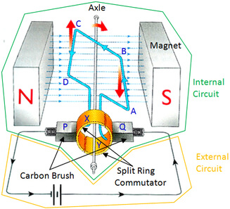
Understanding DC Motors
A DC motor converts electrical potential energy to kinetic energy using a current carrying coil in a magnetic field.
- DC is supplied to the motor
- The coil experiences torque $(𝝉 = nIAB \cdot\sinθ)$ due to the interaction of the external Magnetic field with the current’s Magnetic field $(F = BiL\cdot\sinθ)$ that applies perpendicular forces to opposite ends of the coil, making the coil rotate.
- The coil reaches the halfway point (θ = 0o, normal is parallel) and inertia allows the coil to pass the vertical position.
- Split ring commutator reverses direction of the current so that torque continues in the same direction and coil rotates to complete a full revolution
They work on 1 phase.
Components:
- Stator - stationary
- Motor casing
- Curved magnets/electromagnets
- Input wires
- Carbon brushes
- Stator coils
- Rotor - rotates
- Armature
- Rotor coils
- Split ring commutator
Problems with a brushed DC Motor
- Brushes wear out and need replacement
- Commutator is easily worn thus, shortening motor life
- Sparking at the commutator can be a hazard
IQ: How are electric and magnetic fields related? (Overlap)
Magnetic Flux
Magnetic flux is a measure of the amount of magnetic field (B) passing through a given area (A), visualised as the number of field lines passing through an area. It is given the symbol phi $(Φ)$ and is measured in Webers (Wb) or Tm2. It is given by:
${Φ = B_{∥}A = BA\cosθ}$
Where $Φ$ is magnetic flux (Wb), B is magnetic field (T), B∥ is component of Magnetic field parallel to normal of the coil (perpendicular to plane of the coil), A is surface area (m2), θ is the angle between Magnetic field vector and normal to the area.
$Φ$ is influenced by:
- Magnetic field strength/flux density (B) $\rightarrow$ higher B $\rightarrow$ higher Φ (change either strength of magnet or distance from Magnetic field)
- Area of loop (A)
- Angle of loop to the magnetic field (θ)
- Φ is at a maximum when the field is perpendicular to area/plane of the coil (θ = 0o as normal is parallel to Magnetic field)
- Φ = 0 when θ = 90o and field is parallel to area of the coil (θ = 90o)
Flux is a scalar quantity. If positive flux decreases then change in flux is negative whereas if positive flux increases the change of flux is positive.
Flux of Rotating Coil
When coil is parallel to field lines (horizontal) then there is no flux as there are no flux lines going through the coil (θ = 90o). If coil is rotated by 180o, flux lines have rotated 180o relative to the coil.
Graph of Φ vs t would have a sinusoidal relationship
Magnitude of EMF is greatest when the Φ vs t function crosses the x axis.
Faraday’s Law – EM induction
- When a conductor experiences changing magnetic flux, a voltage will be induced (ε).
- If a voltage is induced in a closed circuit, a current will flow.
- This is called electromagnetic induction.
- Magnetic flux changes if area of the loop changes, angle between the loop and the Magnetic field changes or magnetic field in a closed circuit, a current will flow.
- This is called electromagnetic induction.
- Magnetic flux changes if area of the loop changes, angle between the loop and the Magnetic field changes or magnetic field strength changes.
EMF induced in a moving conductor is given by:
$\orange{ε = BLV = BLV\sinθ}$
Where ε is induced EMF (V), B is the magnetic field strength (Wb), L is length of conductor (m), V is velocity of the conductor’s movement in and out of the field (m/s) multiply by number of loops
RHR For a conducting rod in a Magnetic field
- V =direction of input of positive charged particles (moving conductor) is the thumb
- F = direction of force (direction of voltage) is the palm
- B = magnetic field lines are the fingers
Faraday’s experiments
- Induction with a magnet – Relative motion between a magnet and coil causes a change in Φ inducing an EMF
- Induction with coils – AC current in a primary coil causes a changing Φ, inducing a changing EMF in a secondary coil
- Induced EMF in a circuit caused by changing flux is given by Faraday’s Law of Induction:
$\orange{\epsilon = -N \frac{\Delta\phi}{\Delta t}}$
where ε is the voltage or EMF (V), N is number of turns, $∆Φ$ is change in magnetic flux (Wb), $∆t$ is change in time (s)
Equation has a negative due to Lenz’s Law which states that an induced EMF creates a Magnetic field that opposes the motion that induced it in the first place as per the Law of Conservation of Energy.
As $Φ = BA\cdot\cosθ$, ${\epsilon = -N \frac{\Delta\phi}{\Delta t}}$ where B is magnetic field (T), A is surface area (m2), θ is the angle between Magnetic field vector and normal to the area, $\Delta t$ is change in time (s)
$ε$ is influenced by:
- Magnitude of change in magnetic flux $\rightarrow$ higher change $\rightarrow$ higher EMF (direct)
- Number of turns of coil $\rightarrow$ larger no. of turns $\rightarrow$ higher EMF induced (direct)
- Length of time over which change occurs $\rightarrow$ shorter time/higher frequency $\rightarrow$ higher EMF (inversely proportional)
- When the loop fully enters the Magnetic field, the voltage at the positive and negative terminals are the same on both sides on the loop thus, there is no EMF generated thus, no current flowing.
- If a loop moves within a uniform Magnetic field, there will be minimal change in the number of flux lines in the loop thus, no EMF is generated and no current flows.
- We can take any parameter kept constant out of the bracket eg: $ε = -Acosθ\cdot\frac{B_{f} - B_{i}}{\Delta t}$ if area and angle remain constant
Investigation 1
- Connected air core solenoid to centre reading galvanometer
- Move bar magnet in and out of the solenoid observe effect on galvanometer
- Use RHG rule to determine direction of the current
- Vary the speed and observe changes
Voltage is a form of EMF, but not all EMF are potential differences as EMF accounts for path taken whereas potential difference does not. EMF is a scalar quantity.
Lenz’s Law
Lenz’s Law is a manifestation of the law of conservation of energy. It states that an induced EMF acts to produce an induced current that has an associated Magnetic field that opposes the original change in flux that induced the EMF (opposes motion). Current must flow in a direction that reduces the magnetic flux through the loop and reduces rate of flux change.
Example
As solenoid approaches a magnet with a north pole closest to it, current will flow to create a field with a north pole towards the magnet (use solenoid RHR) hence, repelling the magnet.
If solenoid is leaving a magnet with a north pole closest to it, current will flow to create a field with a south pole towards the magnet (use solenoid RHR) to slow down the change in flux by attracting the magnet.
Eddy Currents
Eddy currents are induced currents formed in bulk pieces of metal due to an experience of changing magnetic flux and the piece of metal forming a closed circuit. Direction of current flow is determined by solenoid RHR and Lenz’s Law where the current flows to form a Magnetic field that opposes the change in magnetic flux.
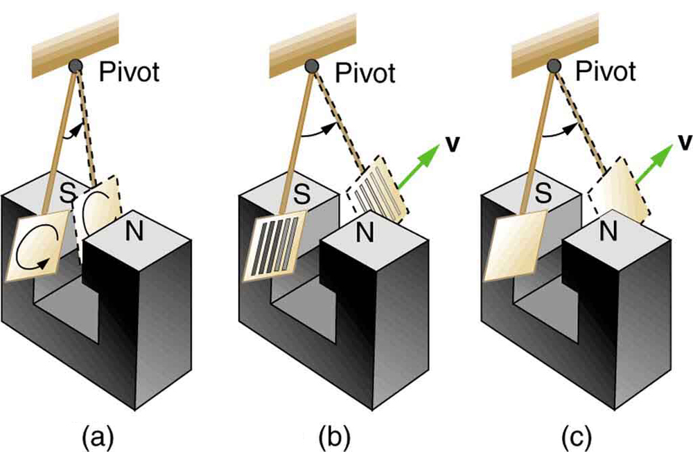
A: As the plate enters the field, the changing magnetic flux creates an induced EMF. Eddy currents (circulating free electrons in metal caused by the induced EMF) are created. According to Lenz’s law, the direction of the eddy currents must oppose the change that causes them.
The eddy currents produce effective magnetic poles (like a solenoid) on the plate, which are repelled or attracted by the poles of the magnet, thus giving rise to a retarding force that opposes the motion of the pendulum.
B: The slots cut out from the metal plate restrict the flow of eddy current with insulating air. The magnetic poles the eddy current creates are thereby weakened as are the retarding forces exerted on them by the external field. The eddy currents formed are more localised and therefore restricted.
Real Life Applications
- Recreational equipment
- Railroad train braking system
- Rollercoaster braking system
- Industrial equipment - Emergency braking of dangerous equipment
- Gym equipment
- Used in rowing machines to change resistance
- Allows for smooth transitions between resistance levels
Problems with Eddy Currents
Eddy currents are often undesirable as they dissipate energy in the form of heat. To reduce energy loss, the moving conductor parts are often laminated. A conductor is laminated by slicing it into thin sections and separating each one with insulating (plastic) layers.
It is effective when the laminations are perpendicular to the plane of the eddy current.
Generators
An AC generator converts kinetic energy to electrical potential energy in the form of alternating current (AC). The coil is attached to an armature/rotor that rotates in the Magnetic field between the magnets. As the coil rotates, the magnetic flux in the loop changes thus, inducing an EMF across the ends of the coil (ε = -N∆Φ/∆t). The ends are attached to conducting slip rings that rotate with the coil and contact the brushes. The brushes connect to an external circuit where the EMF or current is used.
Components of an AC generator:
- Pair of magnets
- Armature
- Rotor coils
- Slip rings – two circular metal rings mounted on end of the armature that are connected to the two ends of the coil. The rings rotate with the coil and contact the brushes.
- Brushes
- Axle
RHR (right hand push rule) for generators
- Thumb points in the direction of where the side will rotate (thumb direction of input motion)
- Palm is direction of the current or force on moving particles
- Fingers are magnetic field
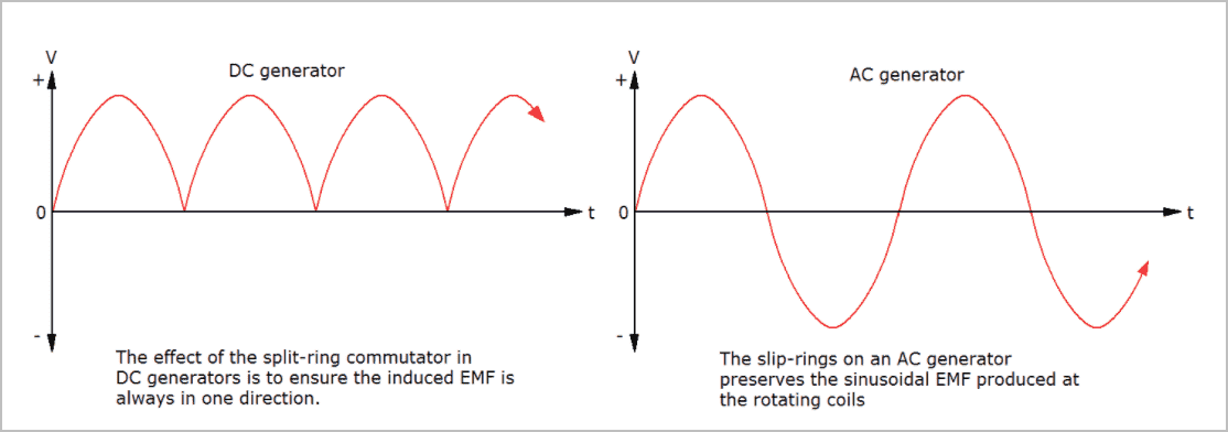
The natural output of a rotating coil is AC as current switches direction every half turn. To make the output DC, a split ring commutator can be used.
Maximum EMF output for an AC generator is given by
$\orange{\varepsilon_{max}= 2\pi\cdot f\cdot n\cdot B\cdot A}$
Where f is frequency rotations per second, n is number of turns, B is magnetic field and A is area.
$I = V/R$ as per Ohm’s Law.
DC Generator
A DC generator converts the output EMF of the generator so that the EMF is always positive. It does so by using a split ring commutator which reverses the current flow in the external circuit every half-turn, instead of slip rings. The output is pulsed, so multiple coils are used to provide a steady current.
Back EMF
- In an electrical motor, current is supplied to a coil in a Magnetic field which experiences a force as per the motor effect thus, turning.
- However, the coil is experiencing a constantly changing magnetic flux due to rotation relative to the Magnetic field and Faraday’s Law states that a changing magnetic flux induces an EMF in a conductor.
- As a result, the self-generated EMF produced in the motor opposes the input EMF as per Lenz’s Law. This is called the Back EMF.
Back EMF reflects the law of the conservation of energy in that it can never exceed input EMF.
Back EMF and Current
The net EMF that causes the current in the coil is a result of the difference between the input EMF and back EMF.
As per Ohm’s Law, $P = VI$, a higher back EMF causes a lower current given a constant P.
Influences on Back EMF
- As rotation speed increases $\rightarrow$ back EMF increases (direct)
- As input EMF increases $\rightarrow$ back EMF increases (direct)
- As load increases $\rightarrow$ more work is done/more power used $\rightarrow$ coil rotates slower $\rightarrow$ back EMF decreases (inverse)
Inrush Current Limiting
Inrush current happens when there is a lag of back EMF at the start thus, causing a spike in current initially before the motor starts spinning. The spike in current can cause the motor to overheat and burnout. To protect the motor, a variable resistor is used on start-up and removed as the coil’s speed increases.
AC Induction Motors
The AC induction motor converts electrical potential energy to kinetic energy through employing Faraday and Lenz’s Law. Unlike, DC motors, it operates on a 3-phase power supply consisting of 3 separate circuits of AC.
Components of an AC induction motor
- Stator
- Multiple pairs (north and south pole) of electromagnetic coils (stator coils) where each pair is connected to a different circuit (1 phase of the 3-phase power supply)
- Rotor
- Squirrel cage – a cage made of conducting bars connected to two conducting rings on either side
- Axle
- Laminated iron core
Note: there are no slip rings or brushes
- Stator coils are connected to a 3 phase AC power supply (120o of a revolution out of phase) which produces a rotating magnetic field thus, providing the change in magnetic flux needed for induction to occur (Faraday’s Law)
- The changing magnetic flux induces an EMF in the squirrel cage rotor which is a conductor $(ε= -N∆Φ/∆t)$. As the squirrel cage forms a closed circuit (that is shorted by the end rings), a current flows.
- As per Lenz’s Law, the current flows to form a Magnetic field that opposes the initial change in flux thus, the squirrel cage rotor attracts the rotating magnetic field thus, causing it to experience a torque in the direction of the rotating Magnetic field
- They are also current carrying conductors in a magnetic field, so they experience a force due to the motor effect, which leads to torque.
The rate of rotation of a rotor of an induction motor is always less than the rate of rotation of the stator field due to a natural lag (not synchronous speed) known as slip that causes the change in flux that makes the motor work.
3 phase induction motor produces a more sustained torque but, 2 phase induction motors also work albeit, rotation is half-turn by half-turn rather than a smooth rotation.
With a load, the torque of an induction motor increases (due to higher current) and speed decreases.
| Alternating Current | Direct Current |
|---|---|
| Low power demand on start Controllable acceleration Controlled start current Reduced power line disturbances Longer life time Adjustable operational speed Adjustable torque limit Simple in construction Cheaper More powerful Induced current (no direct connection) | Easy Installation Speed Control over wide range Quick start/stop High starting torque Linear speed torque Easily used in small appliances Does not require grid power Can be brushless |
- Pin = IpVp=IsVs=Pout thus, Ip/Is = Ns/Np = Vs/Vp
- If Np> Ns then Vp > Vs thus, step-down
- If Np < Ns then Vp < Vs thus, step-up
Ideal transformers make 2 assumptions.
One being that the flux linkage is perfect so that the flux going through the first coil is exactly the same as the flux going through the second coil.
The second being that the transformer is 100% efficient and no energy is lost.
In reality, flux linkage is never perfect and there will always be ‘stray field’.
This stray field can induce eddy currents in nearby materials causing heating and vibration leading to a loss of energy as heat or sound.
Energy is also lost through the heating of transformer coils and core due to the resistance of wires or eddy currents within the ferromagnetic core.
Energy is also lost in the core due to change in direction of the magnetic field (hysteresis) and the process of de and re-magnetisation which causes a loss of energy through heating of the core.
- Use a ferromagnetic core, reduce distance between coils and reduce air gaps to reduce flux leakage
- Use low resistance wire and cooling processes to reduce energy lost as heat
- Laminate the ferromagnetic core to minimise eddy currents
- Use ‘soft’ metal core to reduce energy lost due to Hysteresis
- Step-up transformers are used at power stations to increase the voltage to reduce power loss during transmission due to resistance.
- Step-down transformers are used in electricity substations to reduce the voltage for consumer use.
- Richard, F. (2007, July 14). Electromagnetism and optics: An introductory course [University Page]. Richard Fitzpatrick - University of Texas; University of Texas. https://farside.ph.utexas.edu/teaching/302l/lectures/lectures.html
IQ: How are electric and magnetic fields related?
Transformers
A transformer Is an electrical device that transfers electrical energy from one circuit to another via EM induction. A transformer can accept energy at one voltage and deliver it at another.
A transformer consists of two solenoids placed near each other (conventionally, wound around the same iron core) so that an AC current in the primary coil induces a current in the second coil $(ε = -N∆Φ/∆t).$ As an AC current changes direction, the magnetic flux changes hence, an EMF is induced as per Faraday’s Law. As the secondary coil is also a closed circuit, an AC current with the same period is induced.
The primary coil is the input coil and the secondary coil is the output coil.

Flux linkage
Flux linkage is how much flux from the primary coil’s Magnetic field passes through the secondary coil. Coils need to be matched so that a change in flux in one coil causes a change in flux in another.
There are two ways of doing this: coils can share the same space by placing one inside the other or they can share the same ferromagnetic core. The second method works the best as the primary coil’s current magnetises the full core thus, providing flux linkage between the primary and secondary coil.
An ideal transformer assumes that flux linkage is perfect (no flux leakage) so that flux through any loop is same for both coils, no energy is lost.
Step-up and Step-down Transformers
Converts input alternating voltage to a higher ‘step up’ voltage or lower ‘step down’ voltage.
A step-up transformer has a greater number of turns on the secondary coil. They are used when a greater voltage is required such as at power stations. To not violate the law of conservation of energy, Pin = Pout thus, as voltage increases, current must decrease (P = VI).
A step-down transformer is used to decrease voltage AC is used instead of DC in transformers. It has a greater number of turns on the primary coil hence, as voltage decreases, current must increase for P to stay constant. Phone chargers use these transformers to decrease the supply voltage to that needed by the phone.
Relationship between primary and secondary coils is given by:
$\orange{V_s/V_p = N_s/N_p}$
Where Vp is voltage of primary coil/input voltage (V), Vs is voltage of secondary coil/output voltage (V), Np is number of turns on primary coil, Ns is number turns on secondary coil.
Real Transformers
To improve transformer’s efficiency, you can:
Real Life Applications
Power Loss During Transmission
Power is lost in transmission lines due to heating, usually due to resistance. Power loss is given by:
$\orange{P_{Loss} = I^{2}R = I\Delta V = \frac{\Delta V^{2}}{R}}$
Where P is power loss (W), I is current (A), R is resistance $(\Omega)$, V is voltage (V)